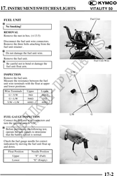
17. INSTRUMENT/SWITCHES/LIGHTS VITALITY 50
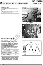
Oil Meter Operation Inspection
Connect the oil meter wire connectors and
turn the ignition switch ON.
Measure the resistance between the wire
terminals with the float at upper position.
Green/Red(+)Black(-) About 340
Before performing the following test,
operate the turn signals to determine
that the battery circuit is normal.
Move the oil meter float up and down to see Oil Indicator Light
if the oil indicator light will go out and
come on.
If the oil indicator light does not light,
check for burned bulb, loose wire or
connector. After correction, check again
according to the method mentioned
above.
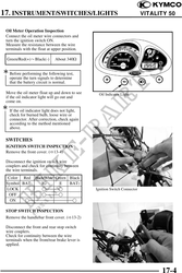
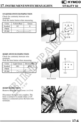
SWITCHES
IGNITION SWITCH INSPECTION
Remove the front cover. ( 13-4)
Disconnect the ignition switch wire
couplers and check for continuity between
the wire terminals.
Color Red Black/White Green Black
Symbol BAT1 IG E BAT2
LOCK Ignition Switch Connector
OFF
ON
STOP SWITCH INSPECTION
Remove the handlebar front cover. ( 13-2)
Disconnect the front and rear stop switch
wire couplers.
Check for continuity between the wire
terminals when the front/rear brake lever is
applied.
17-4