15. STEERING HANDLEBAR/FRONT WHEEL/
FRONT SHOCK ABSORBER MYROAD 700i
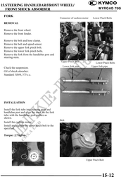
FORK
Connector of cushion motor Lower Pinch Bolts
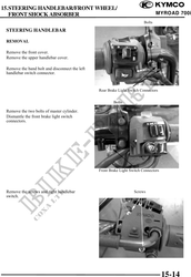
REMOVAL
Remove the front wheel.
Remove the front fender.
Remove the bolt and hose clamp.
Remove the bolt and speed sensor.
Remove the upper fork pinch bolt.
Remove the lower fork pinch bolts.
Remove the fork from the handlebar post and
steering stem.
Upper Pinch Bolt
Lower Pinch Bolts
Lower fork pipe Upper fork pipe
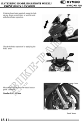
Check the suspension.
Oil of shock absorber:
Standard: SS#8, 375 c.c.
INSTALLATION
Install the fork tube into steering stem and
handlebar post and align the mark on the fork
tube with the handlebar post surface as
shown.
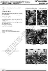
Bolt
Install the cushion motor.
Install and tighten the upper pinch bolt to the
specified.
Torque: 2.7 kgf·m
Upper Pinch Bolt
15-12